
TM 11-5895-856-34-1/EE640-CA-MMI-010/ E154 CPU/TO 31W2-2T-122-1
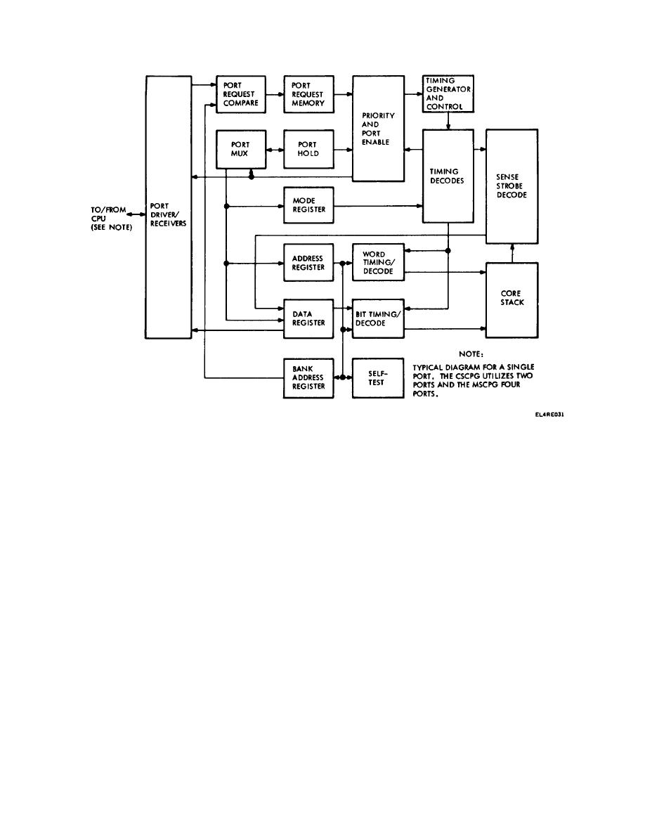
Figure 2-2. MCMU Block Diagram.
transmits the data to the CPU/IOU/RASC, and restores
The MCMU is divided into two major functional areas:
the data unmodified to its former location.
the logic and stack electronics, and the core stack. The
logic and stack electronics contain all the digital and
b. Read-Modify-Write. When operating in this
analog cards which are mounted in a card rack
mode, the memory reads the data in the specified
assembly and are used to process data. In the four-port
address and transmits the data to the CPU/IOUIRASC.
MSCPG configuration, the CPU is connected to port D,
However, the previously stored data is replaced by data
the IOU is connected to port C, and a RASC to each of
from the CPU/IOU/RASC. The new data is then stored
the two remaining ports. For the two-port CSCPG
in the same address location selected at the start of the
configuration, the CPU is connected to port B and the
cycle.
IOU is connected to port A. The signal connection for
c. Clear-Write. This mode of operation causes the
all ports is identical.
memory to clear the contents of the specified address
and replace it with data from the CPU/IOU.
2-11. Operating Modes
d. Memory Test. When operation in this mode, no
Four memory operating modes are available: read-
data is read or written, but the functional status of the
restore, read-modify-write, clear-write, and memory test.
current source is checked as well as the memory bank
a. Read-Restore. In this mode of operation, the
addressing functions.
memory reads the data in the specified address,
2-5

 Previous Page
