
TM 11-5895-856-34-1/EE640-CA-MMI-010/ E154 CPU/TO 31W2-2T-122-1
Section V. INTERFACE CONTROL UNIT
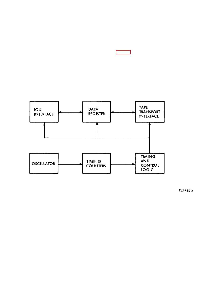
2-18. Magnetic Tape Controller
2-17. General
The magnetic tape controller (MTC) operates as an
The interface control units (IFCU) contain the peripheral
interface controller and buffer between the computer
unit controllers which include (for the message switch),
and up to four magnetic tape transports. Functional
one TTY controller, three line printer controllers, four
organization of the MTC is shown in the block diagram
magnetic tape controllers, and two random access
storage controllers; (for the circuit switch) two TTY
signals which are used to control the various functions
controllers, one magnetic tape controller, and one
performed by the MCT. The timing counters receive the
processor-to-processor interface controller. The power
oscillator output and provide control signals to the timing
supplies for the IFCUs are located within the CPG power
and control logic, which in turn, provide the actual
subsystem group. Power supply status is displayed on
control signals to the IOU interface, data register and
the automatic data processing status and control panel.
tape transport interface. There sessions of the MTC
A block diagram of the CSCPG IFCU is shown in figure
control of the actual transfer of data, commands, and
FO-2; a block diagram of the MSCPG IFCUs appears in
interrupts between the computer and tape transport
figure FO-4.
units.
Figure 2-3. MTC Simplified Block Diagram.
The MTC interfaces with the computer through a
transfer taking place in word-by-byte mode.
The
standard I/O channel. The four message switch MTCs
magnetic tape subsystem undergoes automatic
use the highest priority channel to ensure against data
initialization and orderly shutdown as a function of reset
loss. The proximity of the MTCs to the IOU allow an
signals from the computer. Software can also cause a
IOE to be used for data exchange. A given MTT has a
master reset signal to be sent to the MTC. The program
transfer rate of 20,000 bytes per second with the data
can
2-7

 Previous Page
