
TM 11-5895-856-34-1/ E E640-CA-MMI-010/E 154 CPU/TO 31W2-2T-122-1
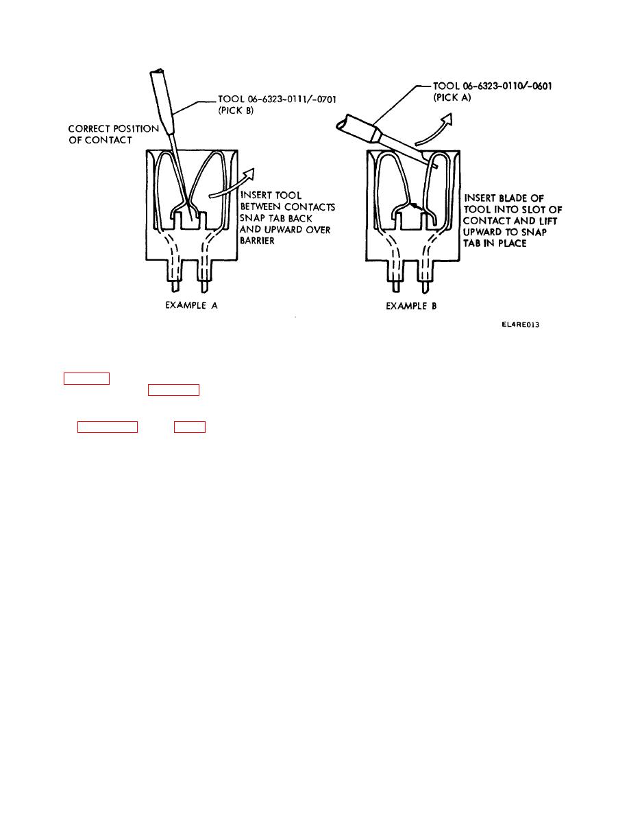
Figure 3-7. Reseating Connector Contact.
locations, and cable interconnection diagrams figure
(6) Insert blade of pick A (06-6323-0110/-
FO-3 and figure FO-5 during the following removal and
0601, table 3-1) into slot of contact and lift up to snap
replacement procedures.
tab in place as shown in figure 3-7, example B.
3-14. Removal and Replacement Procedures
Refer to figures 3-8 through 3-11 for ADP assembly
3-17

 Previous Page
