
TM 11-5805-386-34/NAVELEX 0967-466-1020
printed wiring board is on the right (fig. 2-9).
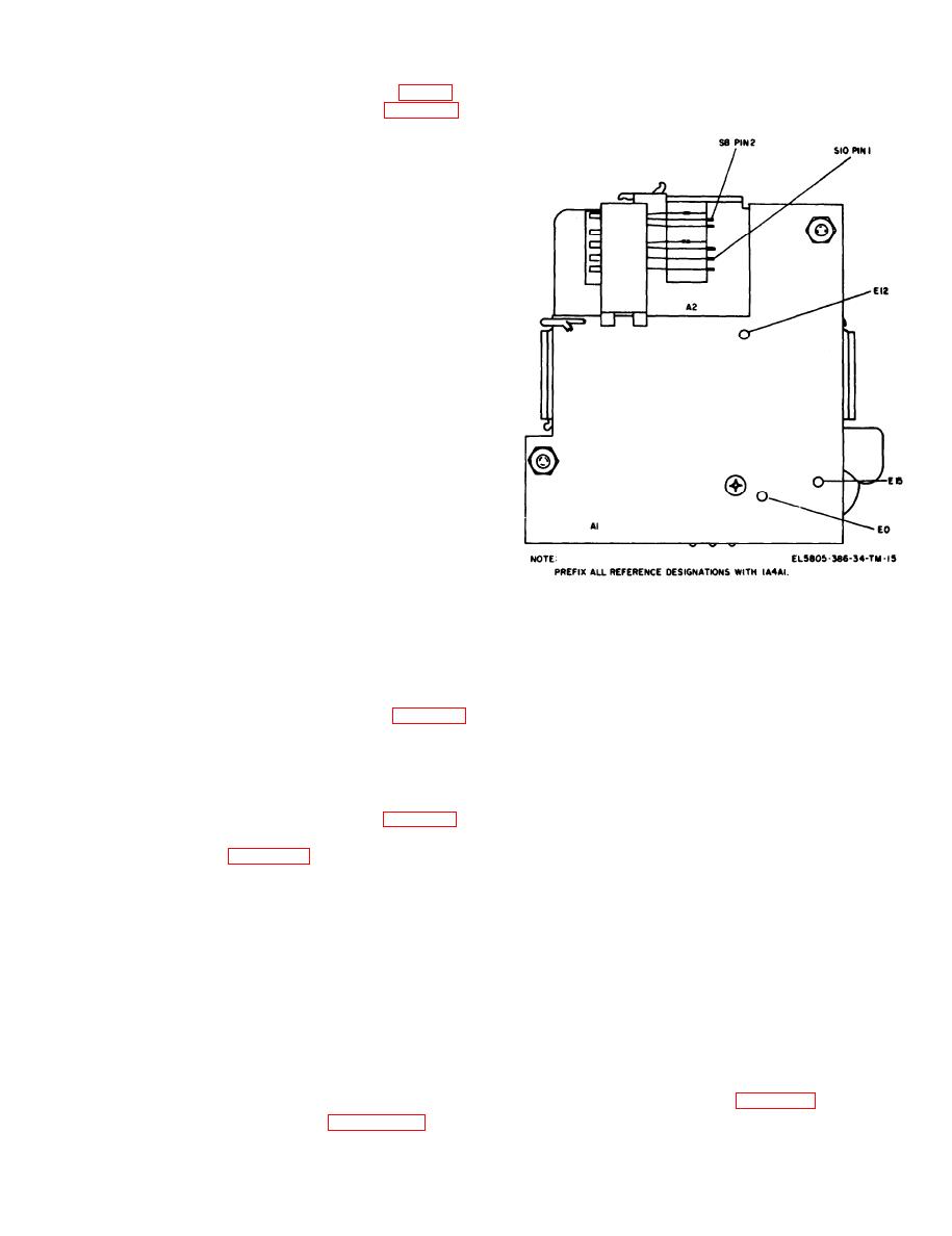
detach wires to keysender tuning contacts located
(1) Remove common module (para 2-9a).
on each of the four sides of keysender assembly.
(2) Place common module on flat surface
with the common printed wiring board facing up.
(3) Release board by removing the four
screws and flat washers located in the corners of
the board.
(4) Tilt the printed wiring board down from
the top to gain access to the wiring terminals.
NOTE
The printed wiring boards are hard-
wired to the circuit at terminals located
along the bottom of the board.
(5) Label each wire with its terminal number
then unsolder the wiring harness and remove the
printed wiring board.
d. Installing Common Module Common
Printed Wiring Board 1A4A2.
(1) Place common module on a flat surface
with side on which board is to be mounted facing
up.
(2) Set printed wiring board on the common
module with mounted parts facing away from the
Al
module and so that the wiring terminals are
adjacent to the wiring harness.
(3) Tilt the top of the board away from the
module and solder the wiring harness (as labeled)
Figure 2-11. Keysender and oscillator assembly terminal
to the terminals.
location.
(4) Press printed wiring board into place and
b . Installing Keysender and Oscillator
see that no wires are pinched between the printed
Assembly 1A4A1.
wiring board and the common module frame.
(1) Place common module on a flat surface with
(5) Secure printed wiring board with the four
wiring harness extended upward through side of
screws and flat washers.
module.
(6) Reinstall common module (para 2-9 b).
(2) Set keysender and oscillator assembly
2-11.
Replacement of Keysender and
adjacent to common module.
Oscillator Assembly 1A4A1
(3) Solder wiring harness (as labeled) to
a. Removing K e y s e n d e r a n d O s c i l l a t o r
terminals.
Assembly 1A4A1.
(4) Insert screw with washer through the
(1) Remove common module (para 2-9a).
front panel hole next to the OFF-LOUD control,
(2) Release common module printed wiring
slide spacer over screw, and hold in place.
board 1A4A2 (para 2-10C (1) through (4)).
(5) Carefully move keysender and oscillator
assembly through side of common module frame
NOTE
with pushbuttons 1, 2, and 3 located toward top
Do no unsolder any connections.
of front panel.
(6) Position keysender and oscillator
(3) Release k e y s e n d e r a n d o s c i l l a t o r
assembly over the screw and spacer and secure
assembly from the front panel by removing the
with washer and nut.
two screws (located on front panel, one on each
(7) Align the other mounting hole with the
s i d e o f k e y s e n d e r ) , spacer,
washers and
corresponding mounting in the front panel; insert
associated nuts.
screw with washer through the front panel and
(4) Carefully remove keysender and
secure with washer and nut.
oscillator assembly from front panel and draw it
(8) Tighten both nuts.
through space between module case and tilted
(9) Install common printed wiring board to
common printed wiring board.
left side of common module (para 2-10 d (4) and
(5) Tag and unsolder only wires connected
(5)).
to terminals identified in figure 2-11. Do not
2-19

 Previous Page
