
TM 11-5805-386-34/NAVELEX 0967-466-1020
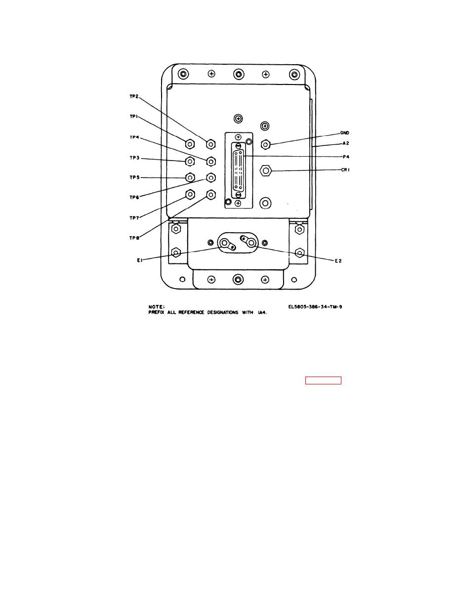
Figure 2-9. Common module rear panel, parts location.
not initially defined, use the operational per-
2-5.
Organization
of
Troubleshooting
formance test (para 2-7) to determine trouble
Procodures
symptoms.
a. General. The first step in servicing the
(2) Refer to the wiring diagrams for point. to-
CV-1919A/G is to determine if a module is
point continuity checks.
defective. Use module replacement to determine
whether defect is in module or converter chassis.
(3) Connect TA-341(*)/TT send pair
Further troubleshooting localizes the fault to a
t h r o u g h TS-402(*)/U to channel under test
printed wiring board or panel-mounted part.
RECEIVE binding posts and RECEIVE pair to
b. Visual Inspection. Inspect the modules and
corresponding SEND binding posts, Set
printed wiring boards for burned components,
TS-402(*)/U for 24 dB attenuation.
broken or loose leads and defective solder con-
2-6. Troubleshooting Charts
nections. These faults may often be located by
The following charts list the malfunctions,
sight or smell.
probable causes, and corrective actions commonly
c. Troubleshooting.
associated with the CV-1919A/G when
(1) The troubleshooting chart lists symp-
troubleshooting. The chart in a below provides
toms of possible troubles, probable causes, and
information concerning trouble on all channels,
corrective action. The voltage and resistance
and the chart in b below provides information
charts provide some of the information referenced
concerning trouble on any one channel.
in the Corrective action column. If the trouble was
2-13

 Previous Page
