TM 11-5805-356-34-1
DIRECT SUPPORT MAINTENANCE INSTRUCTION
Section I. GENERAL
NOTE
Direct support maintenance consists of trouble-
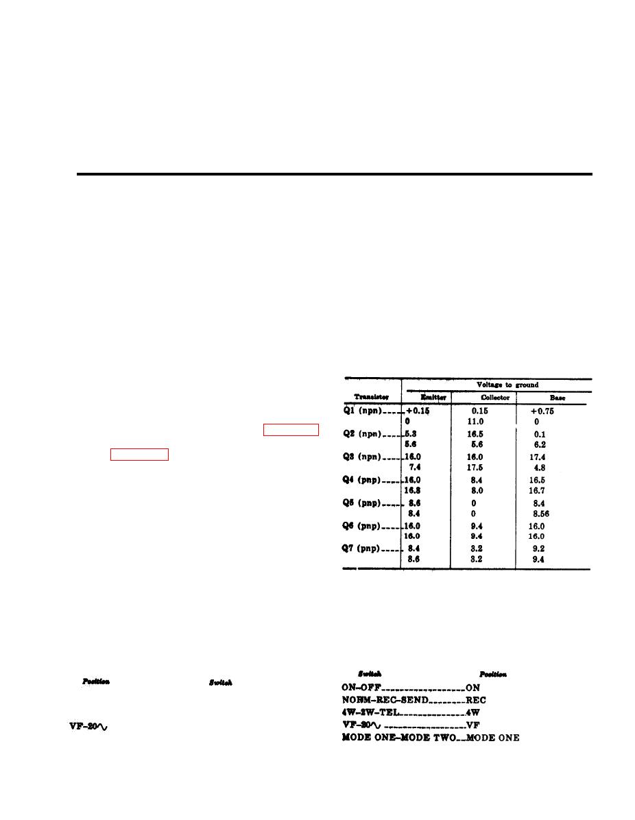
The following chart lists two voltages
shooting the TH-22/TG down to the printed
for each transistor element. The top
circuit (pc) board or a chassis mounted part. It
voltage is measured with a mark input
includes making all required adjustments except
at the SEND jack. This is obtained by
for the output frequency of the send circuit. The
leaving the SEND jacks disconnected.
procedures contained herein are not complete in
The bottom voltage is measured with a
themselves, but supplement the procedures for
organizational maintenance given in TM 11-585
space input at the SEND jack. This is
-256-12. Whenever possible, the organizational
obtained by inserting an open telephone
maintenance procedures should be exhausted be-
plug into the SEND jack.
fore resorting to the direct support maintenance
procedures.
a. Voltage Data. Voltage data for chassis
mounted components are provided by figure 3-1
for components mounted directly to the chassis
and by figure 3-2 for components mounted on
terminal board 1TB1. The following paragraphs
provide voltage data for parts mounted on pc
boards. The control settings and input signals
under which the data were obtained are speci-
fied. The voltages measured at the emitter and
base terminals of transistors may vary by an much
as 20 percent from the listed values. Collector
voltages, however, should not vary by more than
10 percent. The bias (emitter-to-base) voltage ob-
tained should remain very close to that obtained
from the listed values.
(2) Voltage readings for break-in detector
curd 1A2.
(1) Voltage readings for send card 1 A 1 .
(a) Terminate line terminals with 600-
(a) Terminate line terminals with 600-
Ohm load.
Ohm load.
(b) operate Switches as follows:
(b) Operate switches as follows:
0N-OFF-----------------ON
NORM-REC-SEND____NORM
4W-2W-TEL-------------4W
- - - - - - - - - - - - - - - - - - VF
MODE ONE-MODE TWO-MODE ONE


 Previous Page
