
TM 11-5805-356-34-1
(c) Operate RESET switch for 2 seconds.
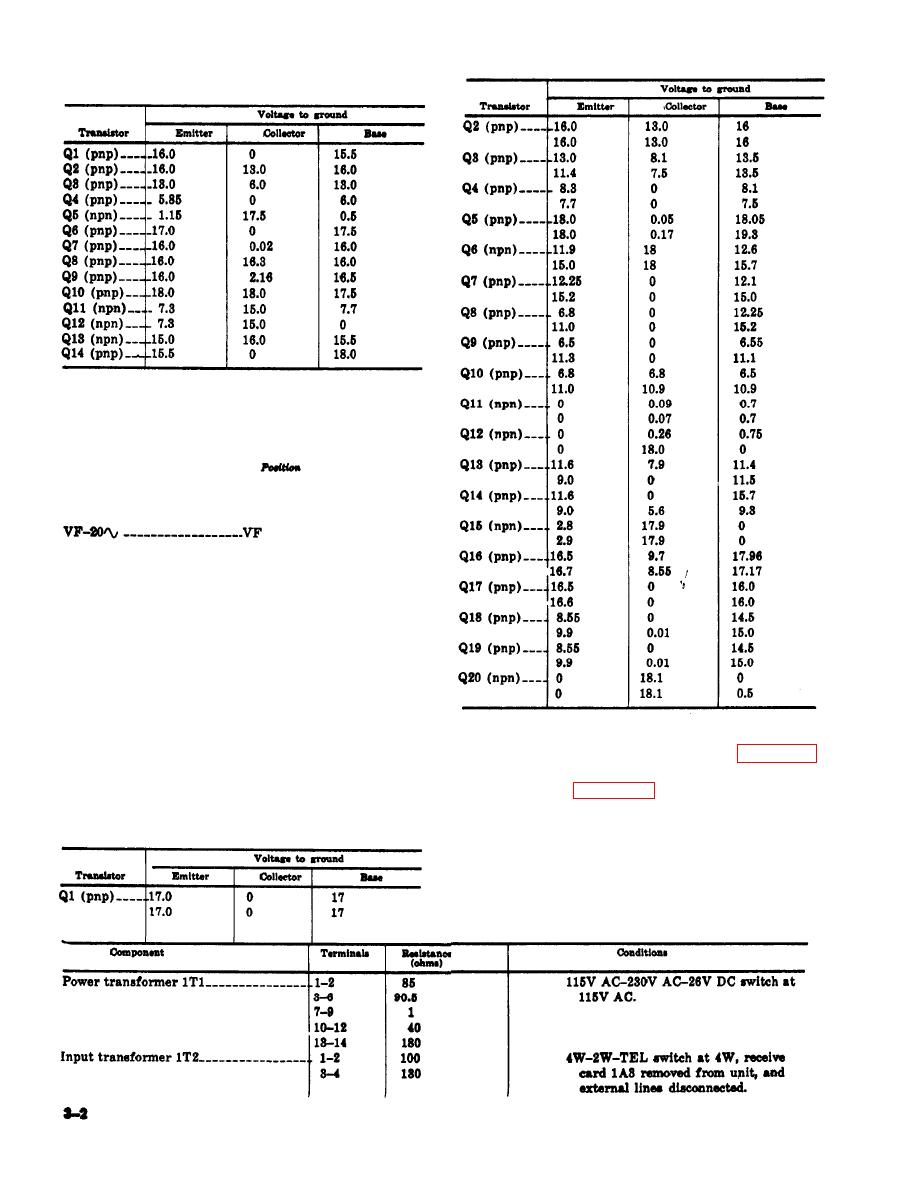
(9) Voltage readings for receive card 1A3.
(a) Terminate line terminals with 600-
ohm load.
(b) Operate switches as follows:
Switch
ON-OFF----------------ON
NORM-REC-SEND___NORM
4W-2W-TEL - - - - - - - - - - - - - . 4 W
MODE ONE-MODE TWO MODE ONE
NOTE
The following chart lists two voltages
for each transistor element. The top
voltage is measured with the controls
set as specified. The bottom voltage for
transistors Q1 through Q14 and Q16 is
obtained with the controls set as speci-
fied, the SEND jacks left disconnected,
and jumper wires connected between
line terminals E3 and E5, and between
E4 and E6. The bottom voltage for
mounted components are provided by figure 3-1
transistors Q15 and Q17 through Q21 is
for those components mounted directly to the
obtained with 4W-2W-TEL switch op-
chassis, and by figure 3-2 for thoee components
erated to 2W and the RING switch op-
mounted on terminal board 1TB1.
erated.
c. Dc Resistance of Transformer and Inductor
Windings. The following chart lists the ohmic
resistance of transformer and inductor windings.
The chart provides the conditions imposed for
the measurement.

 Previous Page
