
TM 11-6625-1668-12
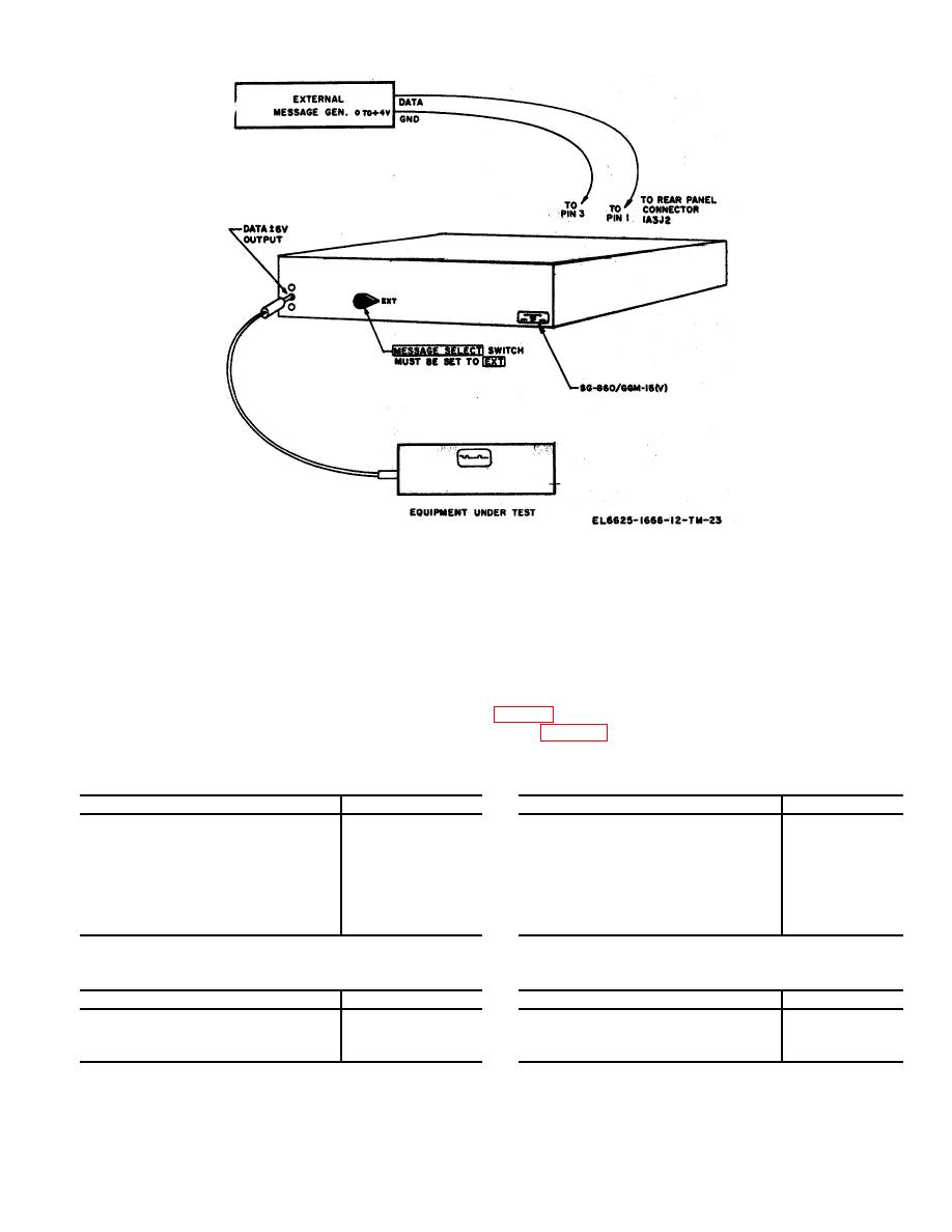
Figure 3-8. External message test setup.
tional functions, however, the actual changes to the circuitry can only be accomplished at a general support or
depot level maintenance facility.
3-8. Analyzer Operating Procedures
The operating procedures contained in this paragraph must be read before attempting to operate the analyzer.
A description of each control function and a typical operating procedure are provided as an aid to the operator.
a. Analyzer TS-2862/GGM-15(V), Preliminary Starting Procedure.
(1) Check power and interface cable connections (fig. 2-9).
(2) Connect the analyzer to the correct ac power source (para 2-6).
(3) For a preliminary test of the analyzer set the controls as follows: The analyzer can be tested
against Generator SG-860/GGM-15V.
Control
Position
Control
Position
POWER switch..................................
OFF
INPUT switch ...................................
HIZ
MARK POLARITY switch ...................
(Negative position)
FILTER switch .................................
OUT
RESET switch....................................
OFF
TRANSITION switch ........................
ALL
DISPLAY MODE switch .....................
DIST (%)
DISTORTION switch ........................
AVG BIAS S/M
THRESHOLD % DISTORTION
00
ALARM RESET................................
DISABLE
switch
CODE LEVEL switch .........................
5
BAUD RATE ....................................
1200
Set the generator controls as follows:
Control
Position
Control
Position
POWER ..........................................
OFF
PERCENT DISTORTION switches ...
25%
P-N switch .......................................
P (polar)
MESSAGE SELECT switch ..............
MSG
DISTORTION SELECT switch .........
BIAS M
CODE LEVEL switch........................
3-14

 Previous Page
