TM 11-6625-1668-12
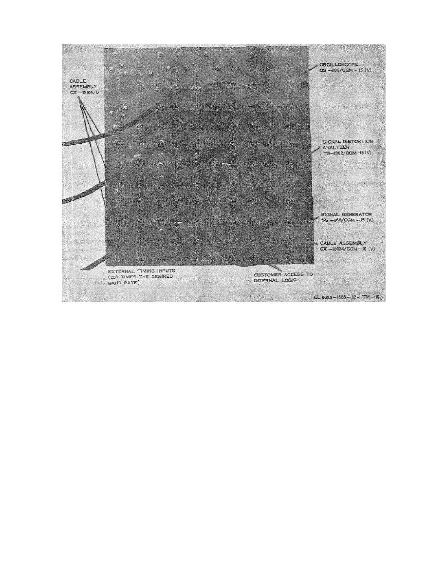
Figure 2-9. AN/GGM-15 (V), cable connections.
(4) An external timing source at 200 times the desired baud rate may be used when the BAUD RATE
switch is set to EXT. and the external source at 6 volts is connected to 1A3J1 (BNC type connector, ground is
shield). The generator may be synchronized with a station master clock at a frequency equal to 2 times the
desired baud rate. The synchronizing signal at 6 volts is connected to 1A3J3-7. The ground connection is
made at 1A3J3-18.
(5) Access to the low level data and clock outputs is provided at the DATA 6/12V jack and the CLOCK
6/12V jack on the front panel. The signal is at the jack tip. The sleeve provides the signal return. Rear
access to the low level data is provided at 1A3J3-3 (signal) and 1A3J3 -4 (return).
b. Analyzer. External equipment connections affecting the analyzer are made as follows:
(1) For a bridging input, polar or neutral, connect the input ground to the BRIDGING input jack sleeve
and the input signal to the BRIDGING input jack tip. Set the INPUT switch to HIz and the MARK POLARITY
switch to + or-as determined by the mark polarity of the input signal.
(2) For series inputs connect the data signal to the SERIES input jack tip and data return to the sleeve.
Set the INPUT switch to the position that indicates the current level and type of input signal. For example: 20N
represents a 20-ma neutral loop.
(3) An external timing source at 200 times the desired baud rate may be used when the BAUD RATE
switch is set to EXT. and the external source at 6 volts is connected to 2A3J1 (BNC type connector, ground is
shield).
2-9


 Previous Page
