TM 11-6625-1668-12
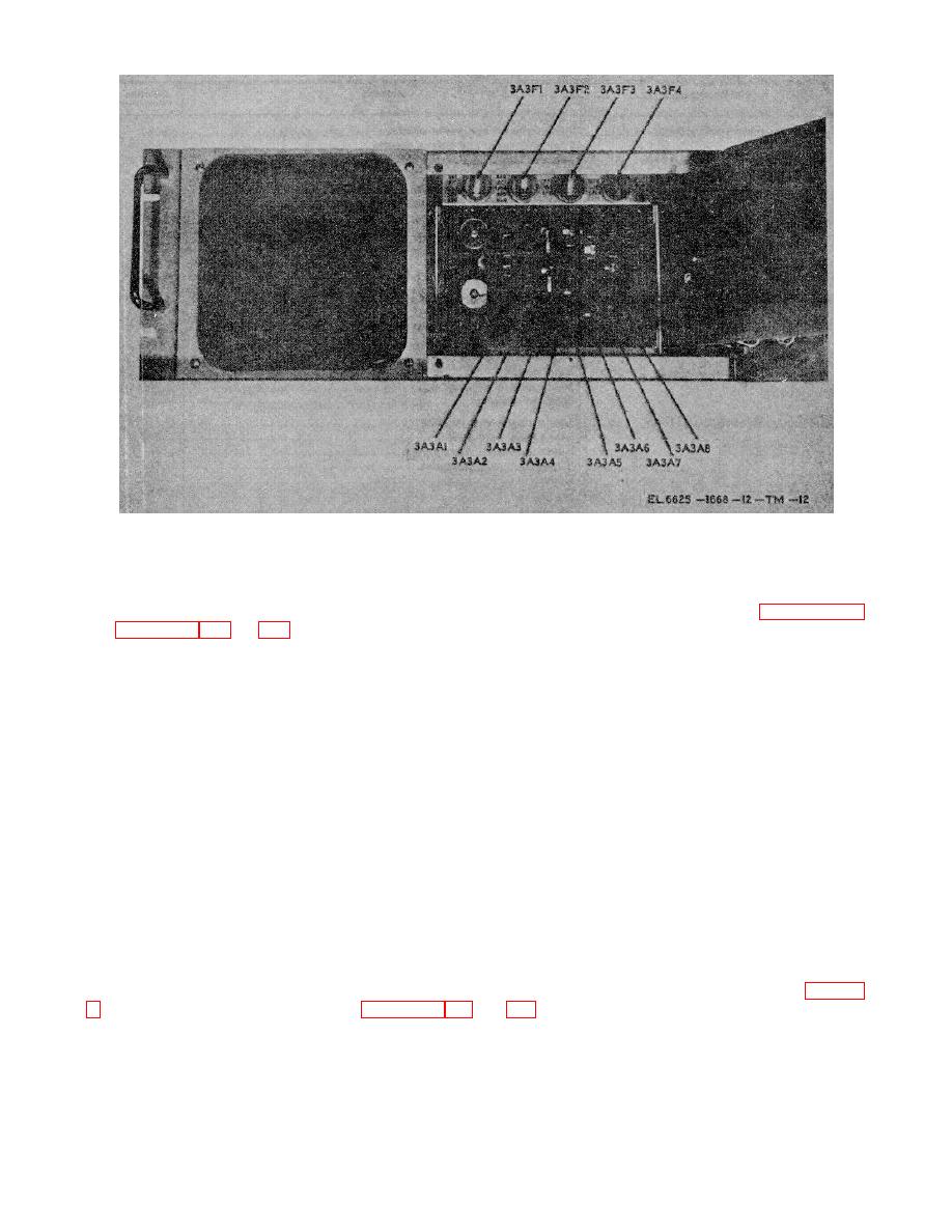
Figure 2-6. OS-206/GGM-15 (V) assembly, card and fuse locations.
(2) Operate each front panel control to assure freedom of movement.
(3) Check front panel locking screws and hinges for signs of damage.
(4) Open and lock front panel, and check the position of each plug-in assembly. Refer to paragraph 2-3
and figures 2-4, 2-5 and 2-6 to check each plug-in assembly for proper location.
(5) Check each plug-in assembly for secure engagement with the appropriate connector.
NOTE
An extractor handle located on the extender assembly is supplied with each major
component for removing and replacing plug-in assemblies. Attach the extractor handle to
the two holes on the front edge of each assembly and pull straight out to remove. To install
plug-in assembly, place the assembly into the appropriate guide rails and firmly push into
place to engage the connector.
e. Inspect the test set case for dents that may interfere with the insertion of the major components.
f. Inspect the dolly for free wheeling ability and firm support of the test set.
2-4. Reference Designations
a. The plug-in assemblies for each of the major components are identified by reference designations which
include the assembly number. The first number of the reference designation, 1, 2, or 3 refers to the major
component generator, analyzer, or oscilloscope respectively. The second part of the designation refers to the
chassis, A1, A2, or A3. The last part of the designation is the assembly number, A1, A2, A3 etc. The complete
reference designation for plug-in assembly 1 of the generator is 1A2A1, the analyzer, 2A2A1, and the
oscilloscope, 3A3A1.
b. The plug-in assemblies for each major component and their reference designations are listed in table 2-
2-5


 Previous Page
