
TM 11-6625-166-12
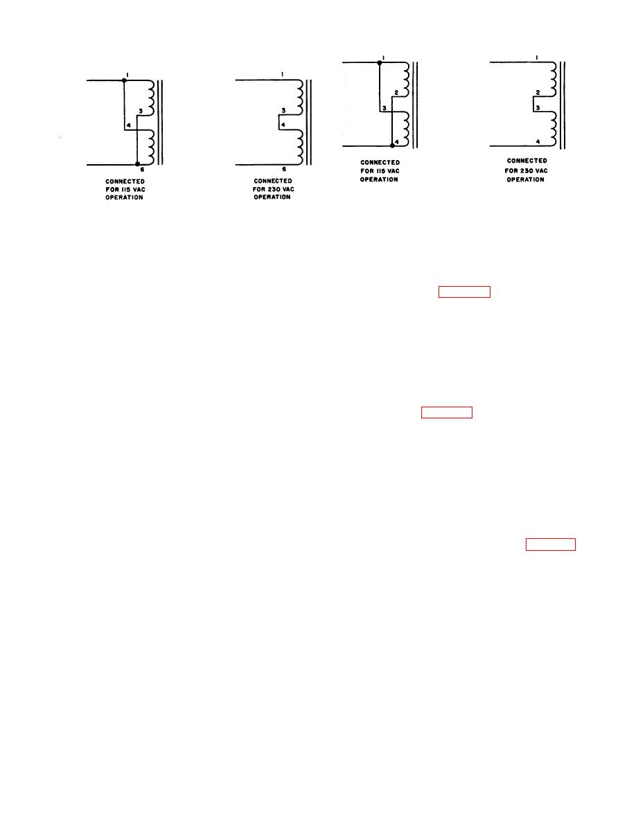
A. GENERATOR AND ANALYZER POWER
B.
OSCILLOSCOPE POWER TRANSFORMER PRIMARY
TRANSFORMER PRIMARY HOOK-UP
HOOKUP
C.
Figure 2-7. Power transformer strapping options.
(2) Position the analyzer in the rack above the generator and secure with screws.
(3) Position the oscilloscope above the analyzer and secure with screws.
(4) Connect the interface cable to the rear of the units as illustrated in figure 2-9. Each plug on the
cable is labeled with a reference designation that corresponds with the appropriate rear panel jack.
Connect as follows:
NOTE
It is important to make proper connections or damage may result.
3A4P2 to 3A4J2
2A3P3 to 2A3J3
1A3P2 to 1A3J2
(5) Connect the power cables to the rear of the units as illustrated in figure 2-9. Three identical power
cables are supplied and may be connected to the units in any order.
Connection is made to the following rear panel jacks:
3A4J1
2A3J4
1A3J4
2-8. External Equipment Connections
The following paragraphs detail the external equipment connections made to the test set for normal operation.
Access to additional logic through the rear panel connectors is provided but not intended for use by the
operator. Internal strapping options that affect the external equipment connections are discussed in chapter 3.
For additional information see the appropriate technical manual.
(1) For high level polar operation, front or rear access, connect the positive battery lead to 1A3J3-16,
the negative battery lead to 1A3J3-17, and battery common ground to 1A3J3-15. Set the P-N switch on the
front panel to P (polar). Jumper 1A3J3-11 to 1A3J3-12 for front panel access through the DRY CONTACTS
jack. Rear access is provided at 1A3J3-9. The marking sense is reversed by connecting the negative battery
lead to 1A3J3-16 and the positive battery lead to 1A3J3-17 or by changing the internal strapping on assembly
1A2A2.
(2) For high level neutral operation front panel access, set the P-N switch on the front panel to N
(neutral) and jumper 1A3J3-11 to 1A3J3-12. For rear panel access, remove the jumper from 1A3J3-11 and
1A3J3-12 and connect the neutral loop to these two pins. The output is available at the DRY CONTACTS jack
in both front and rear access configurations.
(3) Externally stepped character release operation is accomplished by setting the CHARACTER
RELEASE switch to EXT. and connecting a -60-volt dc step pulse at 2 ma to 1A3J3-6. The ground connection
is made to 1A3J3-18. The repetition rate of the pulse must be related to the character length for the selected
baud rate. For example) to step a signal at 50 baud requires that the minimum time between step pulses be
140 milliseconds.
2-7

 Previous Page
