
TM 11-6625-1668-12
deflection.
i. Set the analyzer INPUT switch to I CAL and adjust 2A2A6-R11 to display equal deflection above and
below the reference line.
NOTE
Be careful not to change the settings of the oscilloscope VERTICAL VOLTS
(MA)/VARIABLE potentiometer for the rest of this procedure.
j. Set the VERTICAL VOLTS (MA) /CM switch to 2.
k. Set the analyzer INPUT switch to 20N.
I. Connect Power Supply PP-3941/G to the SERIES INPUT jack and adjust for zero current (use sleeve as
return).
m. Adjust the oscilloscope VERT POS control to position the sweep to the zero center reference line on the
graticule of the oscilloscope.
n. Set the PP-3941/G output to 2 milliamperes (ma).
o. The sweep should deflect one major vertical division (1 cm) on the graticule in the positive direction. If
it does not, adjust R64 on assembly 2A2A6 to obtain the correct deflection.
p. Repeat steps f and o above to insure the accuracy of the adjustment.
q. Disconnect the PP-3941/G from the SERIES INPUT jack.
r. Set the analyzer INPUT switch to ICAL.
s. Set the oscilloscope VERTICAL VOLTS (MA) /CM switch to 5.
t. The deflection on the crt must be plus (+) and minus ((-)) 2 cm. If it is not, adjust 2A2A6-R1 for the
correct indication.
u. Set the analyzer INPUT switch to 20N.
v. Reconnect the PP-3941/G to the SERIES INPUT jack and check the oscilloscope calibration against the
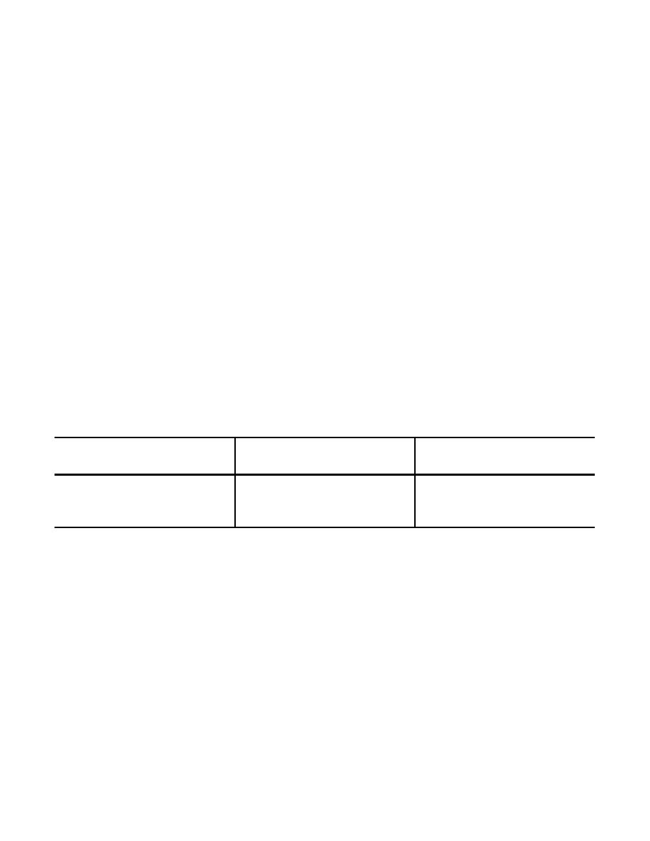
following. chart:
Crt display
PP-3941/G
VERT VOLTS
deflection
output current
(MA)/CM
(cm)
(ma)
switch
2
1
2
5
5
1
10
10
1
20
20
1
w. Set the analyzer INPUT switch to 60N.
x. Set the PP-3941/G output to 80 ma.
y. The crt should indicate exactly 1.6 cm. If it does not, adjust R62 on assembly 2A2A6 until the correct
indication is obtained.
2-11

 Previous Page
