TM 11-5805-386-34/NAVELEX 0967-466-1020
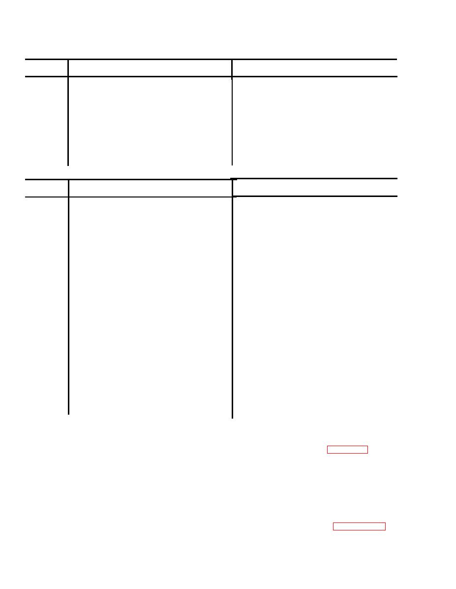
(7) Logic printed wiring board (1A1 through 1A3) A1A2.
Note
Signal
Terminal
Press ACCESS SEIZE pushbutton.
ES
0.3 Vat 2250 Hz on 1.3 Vdc level.
Press ACCESS and DTMF keysender switches one at a
E7
0.6 V
time.
NOTE
Frequency is dependent on
DTMF key selection.
E9
Press ACCESS and RELEASE pushbuttons.
0.3 at 2600 Hz on 1.2 Vdc level.
E11
0.3 V at 570 Hz on 1.4 Vdc level.
Lift TA-341(*)/TT handset off hook.
E13
Lift TA-341(*)/TT handset off hook and then return
0.3 Vat 425 Hz on 1.4 Vdc level.
handset to on-hook.
( 8 ) Common printed wiring board 1A4A2.
Note
Signal
Terminal
E8
0.3 Vat 425 Hz on 1.7 Vdc level
0.3 Vat 2250 Hz on 1.7 Vdc level
E9
E1O
0.3 Vat 570 Hz on 1.7 Vdc level
0.3 Vat 2600 Hz on 1.7 Vdc level
E11
Lift TS-341(*)/TT handset off hook. Waveform is a
E13
6.0 V at 10 Hz
square wave.
(TP1)
0.3 Vat 425 Hz on 0 Vdc level
E14
(TP4)
0.3 Vat 2250 Hz on 3.0 Vdc level
E15
(TP7)
Lift TS-341(*)/TT handset off hook. Waveform is a
6.0 Vat 0.167 Hz on 0 Vdc level
E16
square wave with a duration of 2 seconds low l nd 4
(TP2)
seconds high.
0.3 Vat 2600 Hz on 3.0 Vdc level
E17 (TP6)
0.3 Vat 570 Hz on 3.0 Vdc level
E18 (TP5)
1.8 Vat 2250 Hz on 3.0 Vdc level
E20
4.0 Vat 2250 Hz on 3.0 Vdc level
E21
1.2 Vat 2250 Hz on 3.0 Vdc level
E22
1.8 Vat 570 Hz on 3.0 Vdc level
E23
4.0 Vat 570 Hz on 3.0 Vdc level
E24
1.2 Vat 570 Hz on 3.0 Vdc level
E25
1.8 Vat 2600 Hz on 3.0 Vdc level
E26
4.0 Vat 2600 Hz on 3.0 Vdc level
E27
1.2 Vat 2600 Hz on 3.0 Vdc level
E28
1.6 Vat 425 Hz on 3.0 Vdc level
E29
3.8 Vat 425 Hz on 3.0 Vdc level
E30
1.1 V at 425 Hz on 3.0 level
Lift TA-341(*)/TT handset off hook. Waveform is a
E31
6.0 V at 10 "Hz
square wave- 2 sec on, 4 sec off.
E32 (TP3)
2-3. Supporting Illustrations
mounted part. The parts location drawings
The schematic and wiring diagrams supplement
identify the chassis-mounted parts of the case and
the voltage and resistance charts for tracing
the channel modules. Refer to figures 2-1 through
..
circuit faults to a printed wiring board or chassis-
2-9 and FO-1 through FO-4.
Section II. TROUBLESHOOTING
or resistance measurements at channel test points
2-4. General
Troubleshooting at direct and general support
and printed wiring board terminals. Refer to the
maintenance isolates a fault to a module, a
voltage and resistance charts in paragraph 2-3 for
subassembly, or a panel-mounted part. The
these measurements.
troubleshooting chart refers to signals, voltages
2-4


 Previous Page
