
TM 11-5805-386-34/NAVELEX 0967-466-1020
channel modules
Common module
1A1 through 1A3
1A4
Term
commmon
Logic
No.
A2
Analog
A1A12
A1A1
INF
250K3 2
E11
20K
4400
(TP8)
E12
16K
(TP1)
250K 2
E13
5300
(TP4)
(TP4)
17K
E14
9K
(TP7)
20.5K 2
E15
18K
7000 1
(TP2)
(TP2)
E16
9K
(TP6)
12K
(TP5)
E17
8500
(TP5)
1280
E18
4400
1030
E19
4400
INF
E20
4400
INF
E21
4400
270K 2
E22
4400
270K 2
E23
4600
2800
E24
4400
INF
E25
4400
12.5K
E26
4400
2150
(TP6)
E27
4400
6700
(TP7)
E28
4400
5900
(TP8)
E29
4600
E30
E31
E32
1
Use RX 100 scale.
2
Use RX10000 scale.
3
Depress ACCESS pushbutton while measuring.
pair binding posts of channel under test. Set the
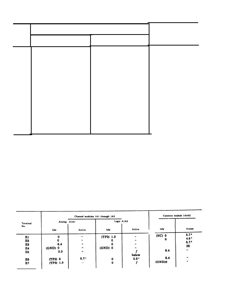
e. Dc Voltage Measurements.
frs-402(*)/U for 24 dB attenuation
(1) The dc voltage measurements are taken
(3) Connect applicable module to equipment
w i t h the TS-352B/U with negative probe
with extender cable (part number 211681 FMC
grounded unless otherwise specified. The readings
15412 or equivalent) for access to test points.
are positive in respect to ground and have a
Equipment should be complete with normal
tolerance of 10%.
complement of modules including the module
CAUTION
under test.
Be sure equipment power is off before
(4) Idle condition is when there are no
removing or reinstalling any module or
incoming or outgoing signals, request for service
the extender cable.
i n d i c a t o r s are extinguished, and plugs are
removed from channel access jacks.
(2) C o n n e c t T A - 3 4 1 ( * ) / T T s e n d p a i r
(5) Dc voltage measurements chart:
through Attenuator TS-402(*)/U to RECEIVE
See footnotes at end of chart.
2-2

 Previous Page
