TM 11-5805-386-34/NAVELEX 0967-1020
Channell modules 1A1 through 1A3
Common module 1A4A2
Analog A1A1
Logic A1A2
Terminal
No.
Idle
Active
Active
Idle
Idle
Action
below
5.72
f below
E8
(TP4) 0
0
5.8 5
1.7
5.83
f below
E9
0
(TP5) 0
1.7
f
below
8
f below
E10
(TP1) 0
1.7
f below
0
E11
1.7
para f
below
0
E12
4.76
(TP8) 3.8
f below
E13
(TP1) 0
2
5.7
f below
(TP4) O
E14
(TP4) 0
5.76
0
f below
E15
(TP7) 3.0
f below
5.7 1
(TP2) 0
E16
(TP2) 0
f below
(TP5) O
5.83
E17
(TP6) 3.0
f below
6.4
(TP5) 3.0
E18
3.0
3.0
E19
0
E20
3.0
0
E21
3.0
6.4 7
0
E22
3.0
6.4 7
0
E23
3.0
0 a n d1
2
6.4
E24
3.0
(NC)5.3 2
0
E25
3.0
0
4.5 22and 11
3.0
E26
(TP6) 0
2.1 and
3.0
E27
(TP7) 0
5.612
3.0
E28
5.7
(TP8) 0
3.0
E29
3.0
E30
3.0
E31
f below
(TP3) 0
E32
1
With PL-51 inserted in channel jack, place
TA341(*)/TT on hook The detected release tone time duration is determined
by the release timer of the TA-341(*)/TT. Reset to IDLE by removing PL-51 from thannel jack.
2
Take TA-341(*)/TT off hook. Reset to IDLE by inserting and removing PL-51 from the channel jack.
3
Connect jumper from TP3 of logic board to pin E 11 of logic board (refer to figure FO-3 for pin location).
4
Depress ACCESS and SEIZE pushbutton.
5
Depress ACCESS pushbutton and any DTM F keysender switch.
6
Depress ACCESS and RELEASE pushbutton-duration of release tone is three to ten seconds.
7
Use AN /USM-281A in place of TS-362B/U for measurement. Insert PL-51 for ACTIVE indication.
8
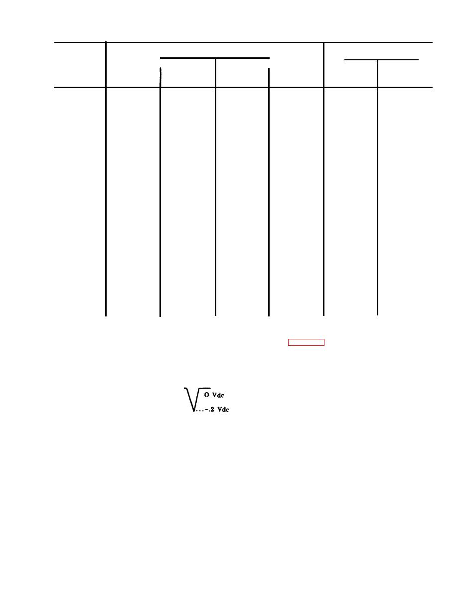
Use AN/USM-281 A and observe power on reset signal for 330 ms negative pulse at power turn on. Waveform observed on
AN/USM-281A should be as follows:
CAUTION
f. Ac Voltage Measurements.
Be sure equipment power is off before
(1) The ac voltages are measured peak-to-
removing or reinstalling any module or
peak 10% using the AN/USM-281A with the
t h e extender cable.
n e g a t i v e probe connected to ground.
(2) Connect Telephone Set TA-341(*)/TT
(5) Connect applicable module to equipment
s e n d pair through Attenuator TS-402(*)/U to
with extender cable (part number) 211681 FM C
channel RECEIVE binding posts of channel
1 5 4 1 2 or equivalent) for access to test points.
u n d e r test. Set the TS-402(*)/U for 24 dB at-
Equipment should be complete with normal
tanuation.
complement of modules including the module
(3) The frequency of the signals is listed as a
u n d e r test.
guide for setting the AN/USM-281A controls
( 6 ) Measurements are made with equipment
a n d not for specific frequency measurement.
i n idle condition and service request indicator
(4) The signal is a sine wave unless otherwise
e x t i n g u i s h e d unless other specified.
specified.
2-3


 Previous Page
