
TM 9-2320-269-20-2
BLOWER ASSEMBLY - CONTINUED
ACTION
LOCATION
ITEM
REMARKS
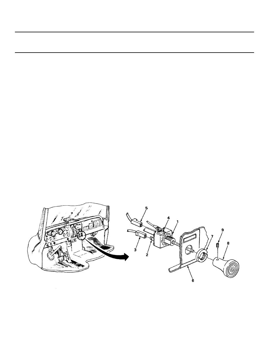
INSTALLATION - CONTINUED
32.
FAN/TEMP
Red wire (3)
a. Check tag for location.
switch (1)
b. Plug in.
terminal L(2)
33.
FAN/TEMP
Orange wire (5)
a. Check tag for location.
switch (1)
b. Plug in.
terminal H (4)
34.
Dashboard (6)
FAN/TEMP
Put into place from behind.
switch (1)
35.
FAN/TEMP
Nut (7)
Screw on, and tighten using hammer and
switch (1) to
chisel.
dashboard (6)
Do not overtighten.
36.
FAN/TEMP
Knob (8)
Put onto switch shaft.
switch
37.
Knob (8) to
Setscrew (9)
a. Screw into hole in knob and switch>L,
FAN/TEMP
shaft.
switch (1)
b. Tighten using 5/64-inch key.
TA229647
2-1268

 Previous Page
