TM 11-5895-856-34-1/E E640-CA-MM 1-010/ E154 CPU/TO 31W2-2T-122-1
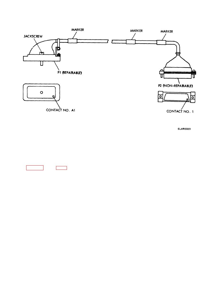
Figure 3-12. Power Cables W201, W213, W235, W650 and W651.
pressure to plunger on extractor tool until the contact is
NOTE
released from the internal shoulder in the connector.
Only P1 of power cable W201 through W213, W235,
W650 and W651 is repairable. P2 is fabricated with
(3) Remove extraction tool and pull contact
epoxy compound and is nonrepairable.
pin from rear of connector.
(4) Cut off contact pin close to pin as
Refer to tables 3-5 through 3-20 for cable wire run lists.
possible.
Perform the following step-by-step procedure for
removal and replacement of contact pin.
b. Stripping and Crimping.
a. Connector (P1l) Contact Removal.
(1) Strip insulation back 0.10 inch from end of
wire.
Check for cut or broken wires and frayed
(1) Loosen connector jackscrew to disconnect
insulation.
connector from unit.
(2) Insert wire into rear of new contact. Wire
(2) Insert extraction tool 06-7699-01 over the
insulation must butt against rear of contact pin.
contact pin to be removed. Apply a firm, steady
(3) Using crimp tool 06-7858-01, insert
contact
3-35


 Previous Page
