
TM 11-5895-856-34-1/EE640-CA-MMI-010/E154 CPU/TO31W2-2T-122-1
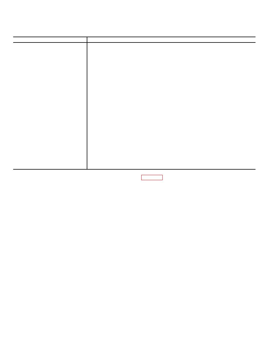
Table 3-2. MTS Test Aid Controls and Indicators
Control or Indicator
Function
Y ADDRESS indicators 1, 2, 4, 8.
Lights (RED) to display binary configuration of MTS Y address counter.
16, 32
X ADDRESS indicators l, 2, 4, 8
Lights (RED) to display binary configuration of MTS X address counter.
TC indicator
Light (RED) to display the status of test clock control logic.
CK indicator
Light (RED) to display the status of clock signals to card under test.
Indicators 1 through 72
Lights (RED) to display the Status of selected control lines dependent on position of
DATA/FUNCTIONALICONT selector switch.
CARD ID indicators 1, 2, 4, 8,
Lights (RED) to display binary code which identifies card under test.
16, 32
STATE indicators 1 through 9, 0
Lights (RED) to display status of MTS state counter.
SELF TEST indicators 0 through
7
Lights (RED) to display status of self test data check logic.
LT pushbutton switch
When depressed, lights all indicators for lamp test.
SCP pushbutton switch
When depressed, enables substate counter to advance one cycle (16 clocks) when stopped
by either SS or BCP toggle switches.
BCP toggle switch
When set to up position, stops substate counter at end of each cycle for single
stepping.
SS toggle switch
When set to up position, stops substate counter at end of cycle if an error has
occurred during that cycle.
Selector switch:
DATA position
Enables indicators 1 through 72 to display data being strobed onto MTS probe.
FUNCTIONAL position
Enables indicators 1 through 72 to display functional errors detected by data
comparison logic.
CONT position
Enables indicators 1 through 72 to display continuity errors detected by data
comparison logic.
NOTE
a. Connect the MTS and MTS test aid as shown in
Refer to TM 11-7010-201-40-5 for
detailed information on MTS Test
Aid.
3-5

 Previous Page
