
TM 11-5895-856-34-1/EE640-CA-MMI-010/ E154 CPU/TO 31W2-2T-122-1
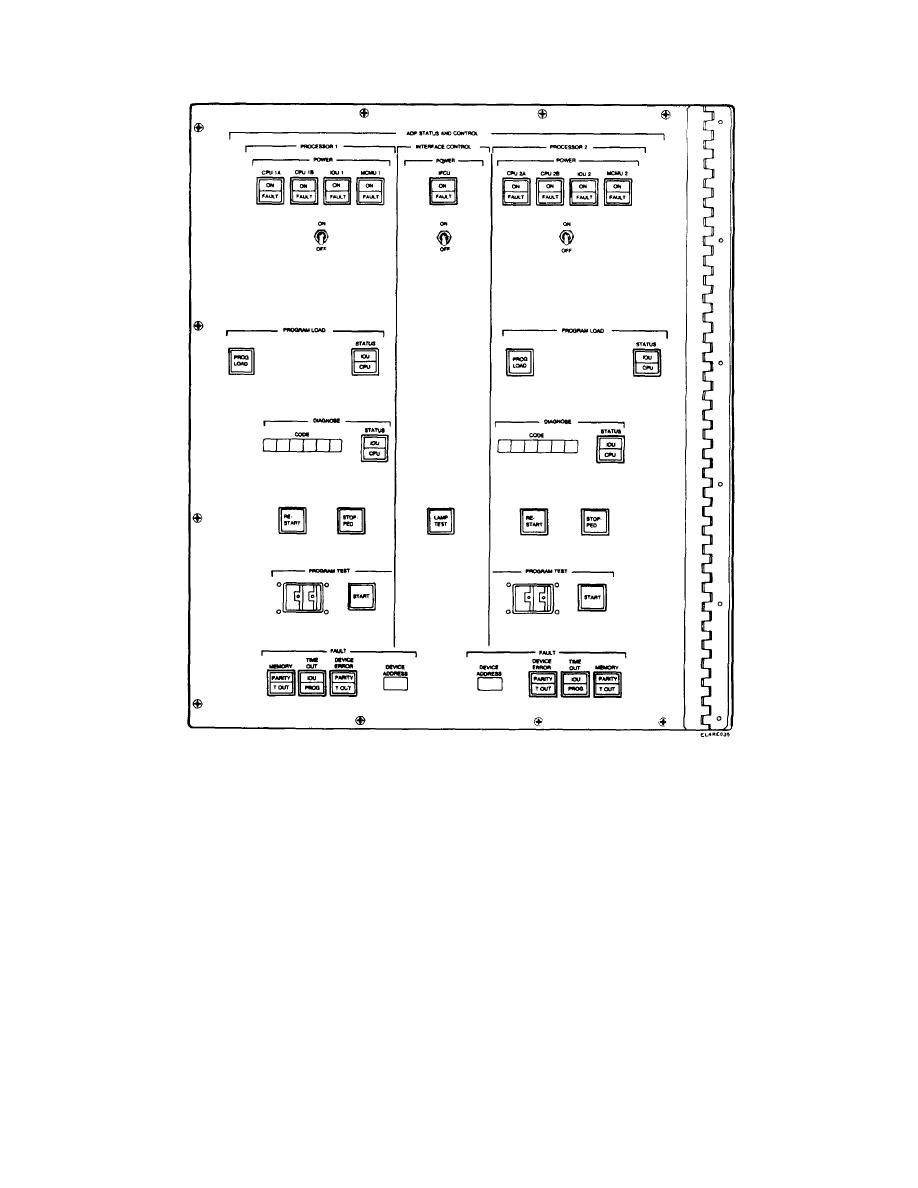
Figure 2-8. ADP Status and Control Panel (Circuit Switch).
Nine indicators on the CSCPG (12 on the MSCPG)
switch is provided to allow selection of the desired
display the status of the dc/dc converters of the power
device.
group. Independent power controls are provided for the
dc/dc converters associated with processor 1, processor
2-24. ADP Status and Control Panel Indicators
2, and the IFCU. (Two additional power supplies are
controlled and monitored at the CS MCMU frame
Many of the status and control indicators are
assembly.) A separate six-digit readout is provided for
programmable. Each programmable indicator has a bit
each processor to display codes that define the location
in the associated monitor register. In all cases, when
of detected faults or for whatever purpose the program
the bit in the monitor register is ZERO, the associated
desires to use them. Controls are also provided for
indicator light goes out. When the bit in the register is
each processor to initiate program load, restart, and
ONE, the indicator is lighted. A functional description of
program test. Parity error, timeout, and device address
ADP status and control panel controls and indicators is
fault indicators are also duplicated for each processor.
provided in TM 11-5805-681-12-1 and TM 11-5805-683-
Since the MSCPG contains six peripheral devices from
12-1.
which a program load can be accomplished, a rotary
2-13

 Previous Page
