TM 11-5805-715-34/EE119-DB-MMI-010-E154 CV3478/TO 31W2-2TTC39-12
secure the twelve screws and washers
b. Connector Pin Removal. To remove
which secure the power supply to the rear
broken pin
panel.
from connector, insert extraction tool 91093-1 over
connector pin and push out.
CAUTION
c. Connector Pin Replacement. To replace
connector pin, perform the following steps:
Ensure circuit breaker is on OFF position.
(1) Crimp connector pin to harness wire
with crimping tool 90222-2.
(5) Connect the ac power cable to the
(2) Insert connector pin into connector
power supply AC INPUT connector.
using a pair of needle nose pliers.
(3) Connect P3(J7) to connector plate
assembly and tighten jackscrews and
3-12. Fabrication of Telephone Patch
replace power supply, step d.
Cord Assembly
d. Power Supply Replacement.
(1) Place power supply to be installed
face down in front of the rear panel.
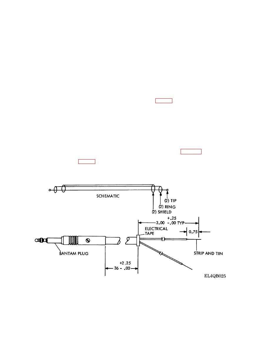
The fabrication of the telephone patch cord used in
the telephone installation to the NIU (TM 11-5805-
CAUTION
715-12) is described as follows:
a. Use telephone patch cord assembly SM-
Observe power supply identification on
A-838684-8.
each wire. Ensure that wires are
b. Cut off one bantam plug from cord as
connected to the right power supply
close to plug as possible.
output terminal.
c. Strip nylon jacket back three inches as
shown in figure 3-5.
(2) Connect lug wires to terminal boards
d. Cut the shield and tape end with electrical
of power supply (fig. 3-4).
tape.
(3) Carefully insert power supply in place
e. Strip the two lead ends 3/4 of an inch and
in the rear panel.
tin.
(4) Using a suitable Phillips screwdriver,
Figure 3-5. Telephone Patch Cord Assembly.
3-8


 Previous Page
