TM 11-5805-715-34/EE119-DB-MMI-010/E154 CV3478/TO 31W2-2TTC39-12
(2) Insert connector pin into connector
a. Rear Panel Removal.
using a pair of needle nose pliers.
(1) Ensure that the circuit breaker on the
(3) Place cable assembly on rear panel
power supply is set to OFF.
and secure panel connector with clinch
(2) Disconnect the signal cables from
nuts. Replace rear panel, step d.
connectors J2 and J3 (Fig. 1-5).
d. Rear Panel Replacement.
(3) Remove the ten screws and washers
(1) Connect P1(J5)/P2(J6) from rear
securing rear panel.
panel to connector plate assembly and
(4) Release the four jackscrews (two
tighten jack- screws.
each) securing P1(J5) and P2(J6) and
(2) Secure rear panel with the ten screws
disconnect from connector plate
and washers removed in paragraph 3-10,
assembly. Remove rear panel.
step a (3).
(5) Remove clinch nuts securing
connectors J2 and J3 to rear panel and
remove cable assembly.
b. Connector Pin Removal. To remove
3-11. Internal Power Cable Maintenance
broken pin from connector, insert extraction tool
91093-1 over connector pin and push out.
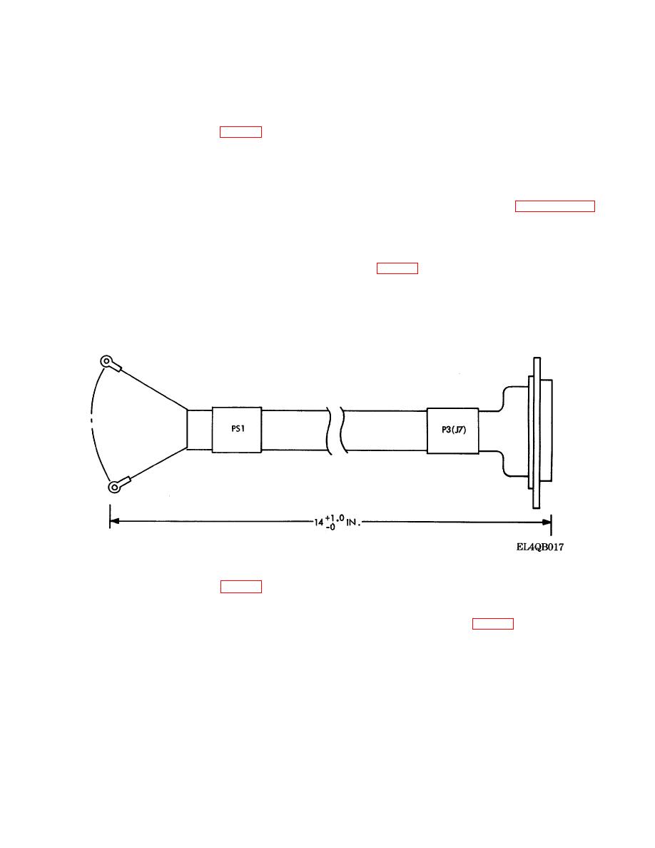
Maintenance of the internal power cable consists of
c. Connector Pin Replacement. To replace
removal and replacement of connector pins on
P3(J7). To perform maintenance on the internal
connector pin, perform the following steps: (1)
power cable proceed as follows:
Crimp connector pin to harness wire with crimping
tool
90222-2.
Figure 3-3. Internal Power Interface Cable.
a. Power Supply Removal (fig. 1-5).
(6) Carefully pull out the power supply
and place it face down.
(1) Set the circuit breaker to OFF.
(7) Remove all wire lug leads from the
(2) Ensure that the external power source
terminal boards (fig. 3-4) of the power
is deenergized.
supply with a suitable flathead
(3) Disconnect the ac power cable from
screwdriver and replace screws and
the power supply AC INPUT connector.
washers in the terminal boards.
(4) Fasten dust caps on respective
(8) Release the two jackscrews securing
connectors.
P3(J7) and disconnect from connector
(5) Remove the 12 screws and washers
plate assembly and remove cable
which secure the power supply to the rear
assembly.
panel of the NIU equipment case.
3-6


 Previous Page
