TM 9-2320-269-20-2
AUXILIARY TOOLS HYDRAULIC DRIVE LINES - CONTINUED
ACTION
LOCATION
ITEM
REMARKS
INSTALLATION - CONTINUED
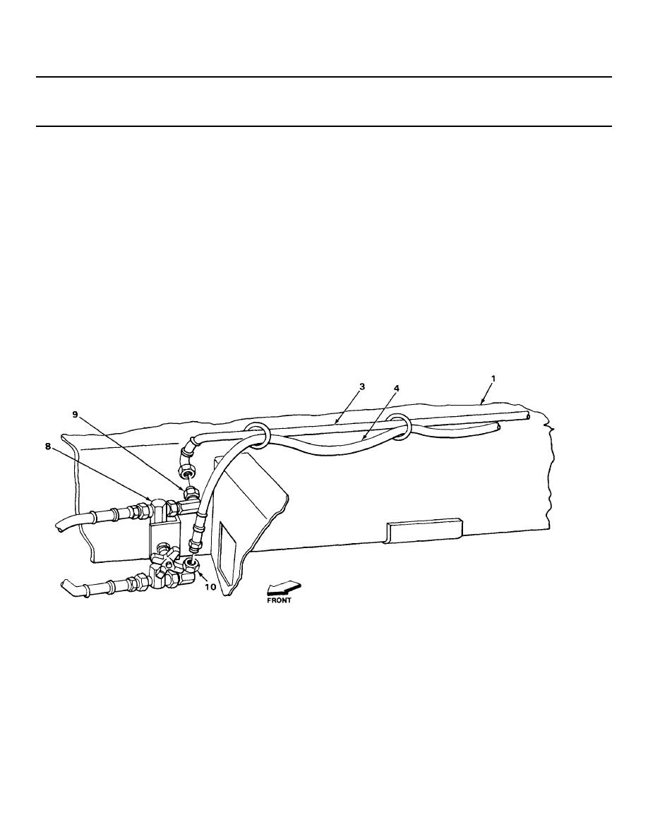
35. Derrick leg (1)
Two needle valve-to-
Pull through guide rings (5) toward
and needle
derrick operator's
front of truck, and put in position at
valve (8)
flow control valve
valve (8).
hose assemblies
(3) and (4)
36. Adapter (9)
Needle valve-to-
a.
Check tag for correct location, and
derrick operator's
take off.
flow control valve
b.
Screw on, and tighten using 7/8-inch
hose assembly (3)
and 1-inch wrenches.
37. Adapter (10)
Needle valve-to-
a.
Check tag for correct location, and
derrick operator's
take off.
flow control valve
b.
Screw on, and tighten using
hose assembly (4)
11/16-inch and 7/8-inch wrenches.
TA229200
2-959


 Previous Page
