TM 9-2320-269-20-2
POLE GUIDE ASSEMBLY - CONTINUED
ACTION
LOCATION
ITEM
REMARKS
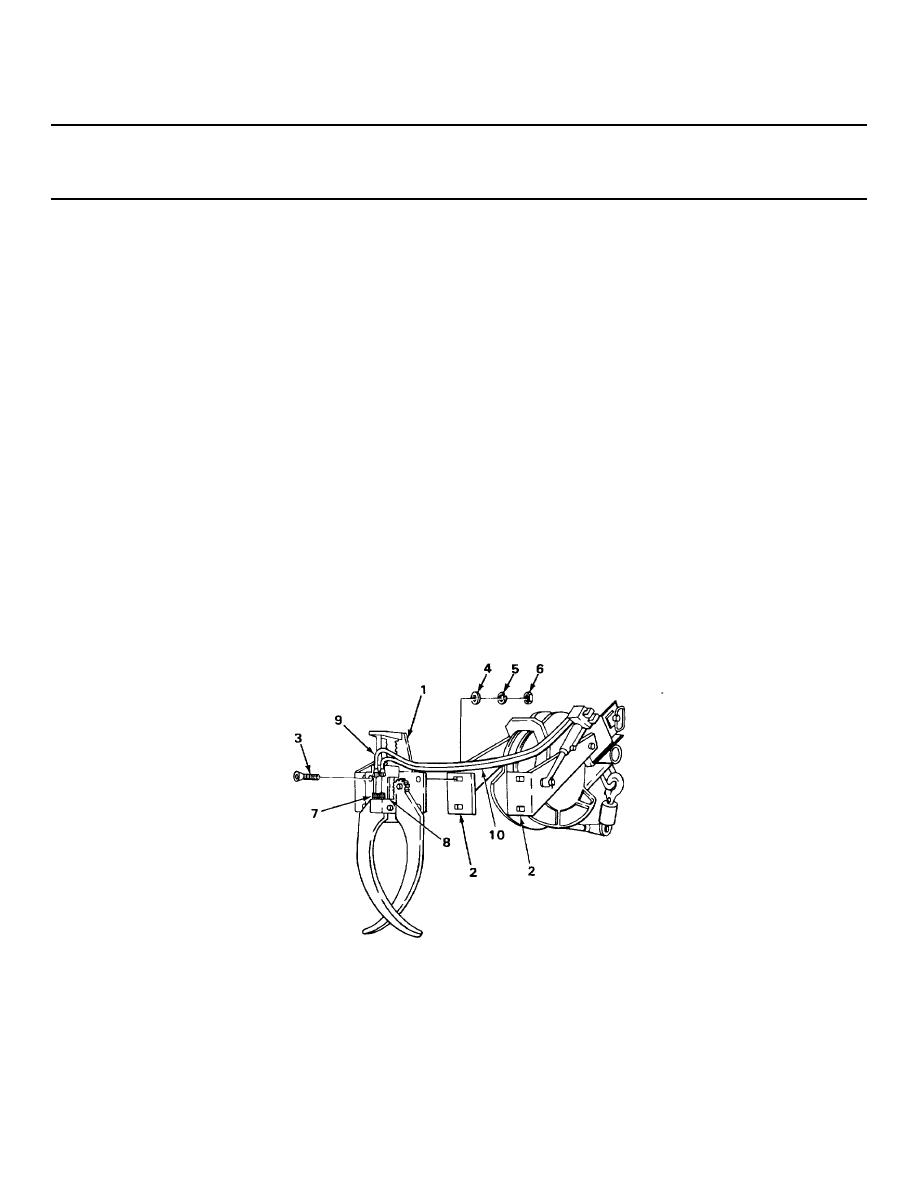
INSPECTION/REPLACEMENT
NOTE
For more information on how to inspect parts, go to General Maintenance Instructions
(page 2-142).
5.
Pole guide
Look for cracks, breaks, bends, and
assembly (1)
chipped or broken teeth.
INSTALLATION
6.
Two arms (2)
Pole guide
Place in position.
assembly (1)
7.
Pole guide
Four screws (3),
a. Screw in until snug using 5/16-inch
assembly (1) and
washers (4), new
key, 3/4-inch socket, and handle.
two arms (2)
lockwashers (5),
b. Tighten to 41 ft-lb (56 N m) using
and elastic
5/16-inch key, 3/4-inch socket,
stop nuts (6)
and torque wrench.
c. Take out wooden blocks.
8.
Two swivel
Two hose assemblies
a. Note locations, and take off tags.
adapters (7) and (8)
(9) and (10)
b. Screw on, and tighten using 5/8-inch
TA229174
2-926


 Previous Page
