
TM 11-5805-356-34-1
c. Signal Substitution for Vf Alarm Circuits
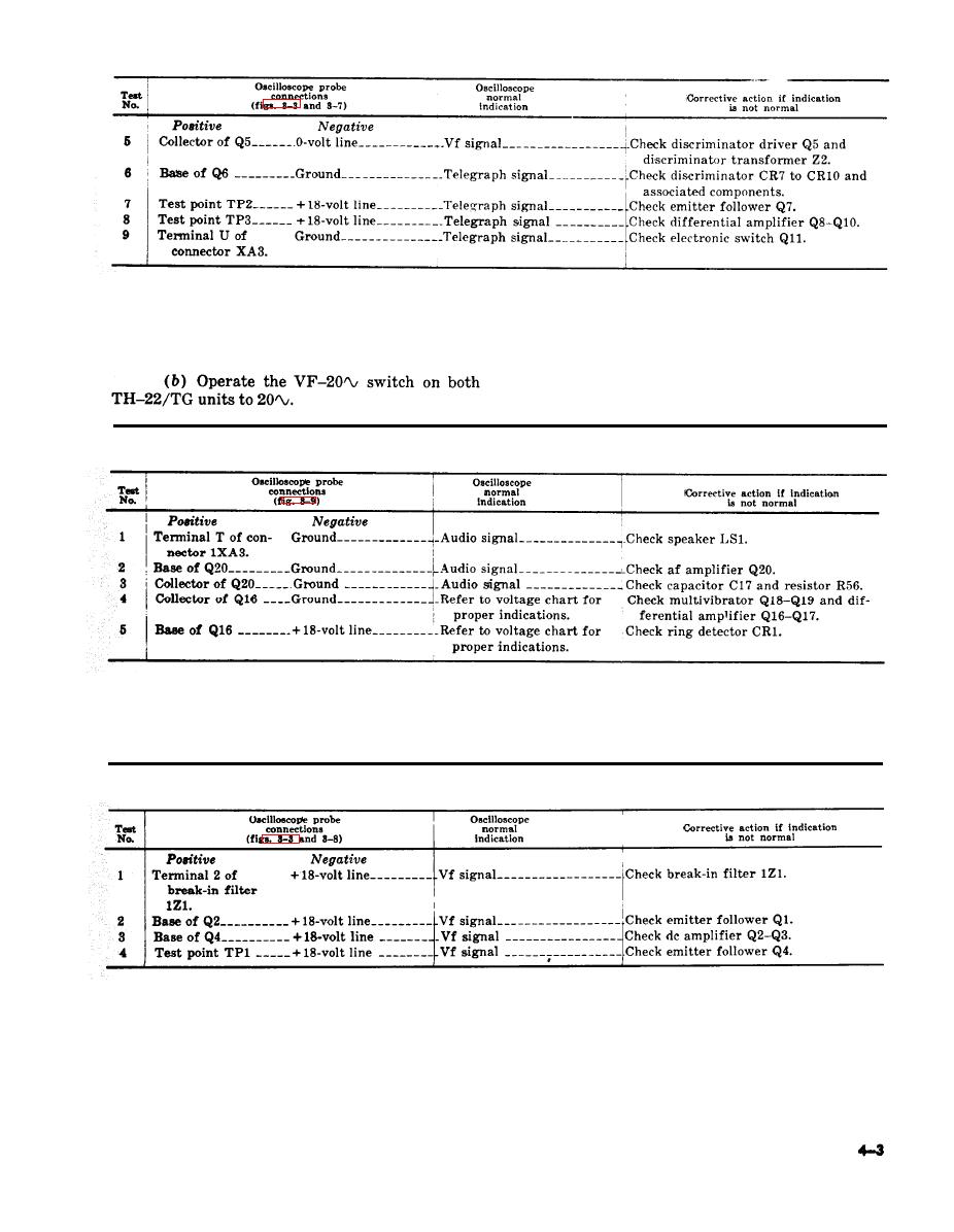
(c) Operate the RING switch on standard
on Receive Card 1A3.
TH22/TG and note that the alarm does not
(1) Procedure.
sound. (If the alarm sounds, the circuits are op-
(a) Perform the procedure given in a (1)
crating normally. )
above.
in the chart ( (2) below).
(2) Signal substitution chart.
(a) Perform the procedure given in a (1)
d . Signal Substitution for Vf Circuits on
above.
Break-In Detector Card 1A2.
(b) Operate the BREAK-IN switch on
the standard TH-22/TG.
(1) Procedure.
(2) Signal substitution chart.
Section IV. MAINTENANCE OF TH-22/TG
when replacing transistors, b below when replac-
ing parts, and c below when repairing pc boards.
The general support repair procedures consist of
replacing transistors and parts, and repair of the
a. Transistor Replacement.
TH-22/TG pc boards. These procedures require
(1) Use a pencil-type soldering iron with a
the use of Electronic Tool Kits TK-100/G and
TK-105/G. Follow the procedures in a below
25-watt maximum capacity.

 Previous Page
