
TM 9-2320-269-20-2
LEFT OUTRIGGERS HYDRAULIC DRIVE LINES - CONTINUED
ACTION
LOCATION
ITEM
REMARKS
INSTALLATION
NOTE
Before installing hose assemblies wrap all external threads with two turns of teflon tape
(page 2-142).
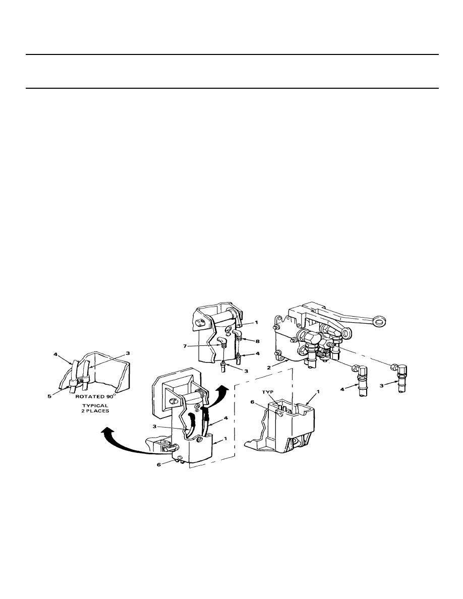
20.
Outrigger
Two outrigger
a. Check all tags for correct locations.
link (1) and
control valve-to-
b. With help from an assistant, and
outrigger control
left front hose
using fish tape, put in position.
valve (2)
assemblies (3) and (4)
21.
Outrigger link (1)
Two screws (6)
a. Take off tags.
and two hose
b. With hoses (3) and (4) positioned at
clamps (5)
adapters (7) and (8) and clamps (5),
screw in, and tighten using 7/16-inch
socket and handle.
22 Two swivel
Two outrigger
a. Take off tags.
adapters (7) and (8)
control valve-to-
b. Screw on, and tighten using 9/16-inch
left front hose
assemblies (3) and (4)
TA229232
2-1009

 Previous Page
