
TM 11-6925-1668-12
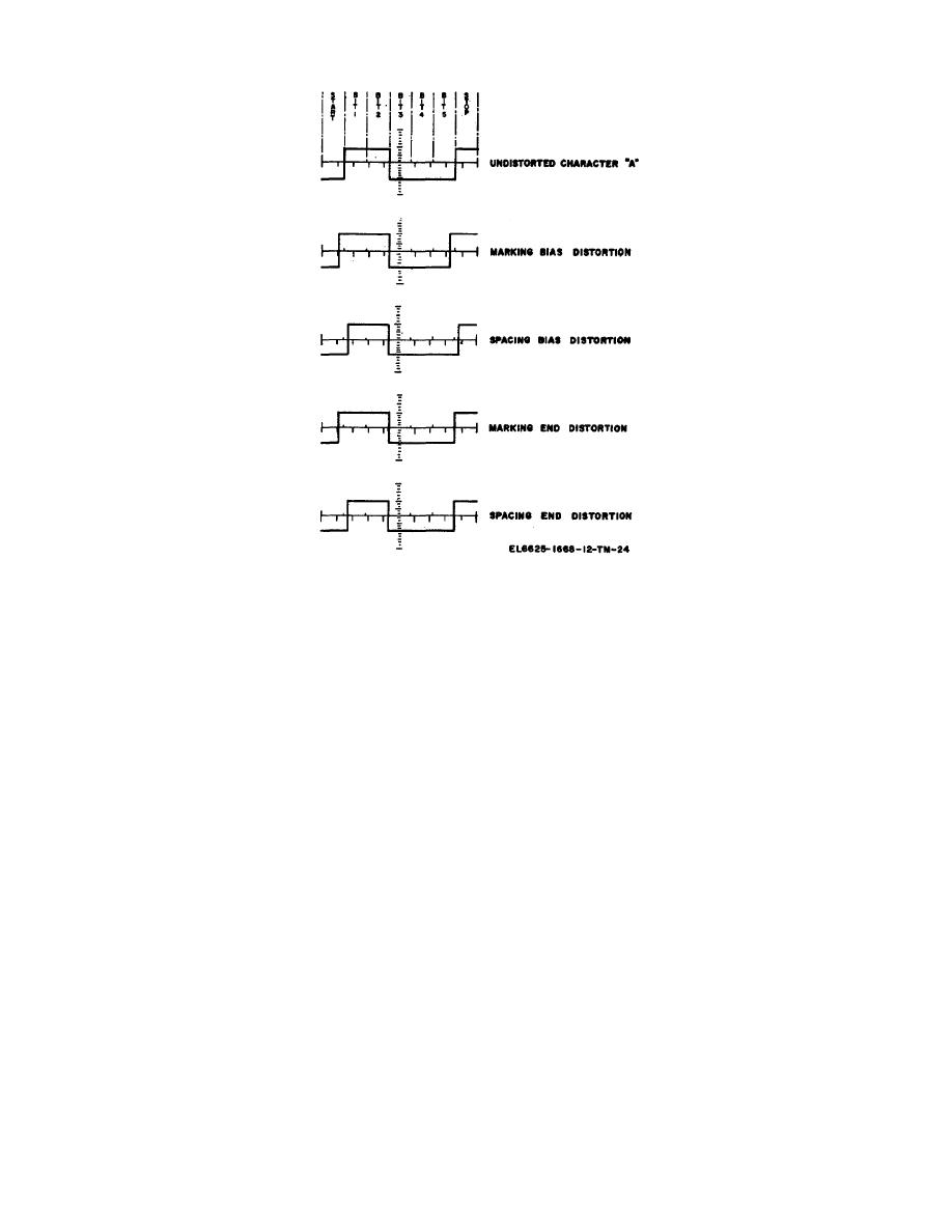
Figure 4-1. Distortion oscilloscope display.
4-8. Analyzer Self-Test (Error Test Mode)
The analyzer is provided with an error test operating mode which is used to self-test the system error code
operation. To perform the error test, the analyzer DISPLAY MODE switch is set to TEST MODE and the
ERROR DEFINER thumbwheels are set to 49. The MARK POLARITY switch is set to the position which
causes the START lamp to illuminate. The generator MESSAGE SELECT switch must be set to EXT. and the
DISTORTION SELECT switch to NO DIST. An operating speed of 1200 bauds is recommended for both
generator and analyzer to reduce the time required for error rate measurement.
NOTE
The position of unmentioned controls will not effect error test operation.
When ac power is applied and the correct position of the MARK POLARITY switch is established the analyzer
will count approximately 10 errors every 9 seconds and indicate an overflow at 99. The overflow indication
denotes that the maximum reading of the nixie display has been reached. To further define errors, set the
generator DISTORTION SELECT switch to BIAS M and the PERCENT DISTORTION switches to 25. Reduce
the setting of the ERROR DEFINER thumbwheel switches to the point where the nixies display a rapid count.
The setting of the thumbwheel switches, at this point, indicates the amount of distortion on any M/S or S/M
transition.
4-9. Cleaning, Painting, and Preservation
Inspect the exterior surfaces of the AN/GGM-15(V). The exterior surfaces should be clean and free of dust,
dirt, grease, and fungus.
a. Remove dust with a clean, soft cloth.
WARNING
Prolonged breathing of cleaning compound is dangerous; provide adequate ventilation.
Cleaning compound is flammable; do not use near an open flame.
4-4


 Previous Page
